


February 2021
The Ultimate Helix IMAGE "Air" - With a little help from my friends
08/02/21 13:11 *HELIX USB CableCable Construction | DiY Cables | *HELIX IMAGE APPROACH | * HELIX IMAGE (Air)
This Page is an overview of the very latest developments and updates to the Helix Cable Geometry
Last Update: 28 February 2022 : The Ultimate Helix IMAGE "Air" Interconnect cables.
Employing UP-OCC bare Solid Silver used for Signal Conductors in separate Teflon tubes
The Ultimate Helix IMAGE "Air" interconnect Double/Single
The performance of this cable is exceptional, providing more details, with a larger and more detailed image having more sense of "Space". Improved dynamics across the board, with many more textures being revealed
The previous developments
NOTE: For Helix Cable/Component compatibility - please see HELIX Q & A
What Others Think
For unsolicited opinions of what other folk think of the Helix Cables please take a look at this link
Duelund conversion to DIY Helix Geometry Cabling
Dielectric Constant - what is it?
During previous developments, it was quite noticeable that selecting wires that had an insulation with a low Dielectric Constant (Dk) for the signal or live wires only resulted in improved sound quality
Dielectric Constant (Dk)…
So the challenge was: how to get the Dk as close as possible to the value of Air?
The adaption to the insulation can be found here…
For Fabrication details please see …
I am currently using The Ultimate HELIX IMAGE "Air" cables and can report that the modifications have resulted in significant and easily discernible audible improvements over the older design.
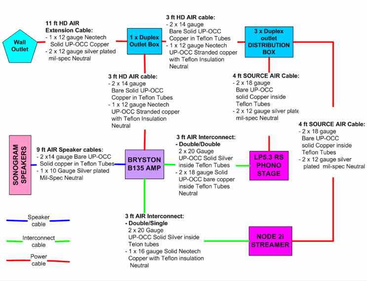
I have listed a few options of wires that can be used for the signal and neutral wires in the detailed fabrication instruction, but the digram below shows which wires I use and for which components
The original helix design concept was to eliminate the parallel conductors commonly used in conventional cable architectures in order to minimizes the noise, proximity effect and Skin effect to imperceivable levels, improving clarity and dynamic performance of the interconnect.
Since those early days, developments include the selection of advanced wire metallurgy, gauge of wire best suited to the task at hand and types of insulation in order to reduce noise to a minimum, which brings us to this moment in time.
The instructions on this web site demonstrates how these cables can be fabricated in the easiest and most cost effective manner in order to achieve extremely high levels of resolution that competes with the very best commercially available products for a fraction of the cost.
Previous adaptions to the HELIX Cable are courtesy of:
Will there be any further updates - probably, because there is always someone, like Bill, Ernst, Jordan and Evgeny that is looking to improve on the capabilities of “The Helix” cable geometry.
If you have any further questions on these upgrades just drop me a line.
Regards - Steve
Last Update: 28 February 2022 : The Ultimate Helix IMAGE "Air" Interconnect cables.
Employing UP-OCC bare Solid Silver used for Signal Conductors in separate Teflon tubes
The Ultimate Helix IMAGE "Air" interconnect Double/Single
- where the 2 x 20 gauge bare UP-OCC solid silver Signal wires are inserted into individual Teflon Tubes.
- the Helix Neutral is a single Neotech 16 gauge solid UP-OCC wire with Teflon insulation
The performance of this cable is exceptional, providing more details, with a larger and more detailed image having more sense of "Space". Improved dynamics across the board, with many more textures being revealed
The previous developments
- 12 December 2021: Helix Power cables are not suitable for use in countries that adopt a "balanced" power grid - such as Norway.
- 4 November 2021 Fine tuning of the Helix IMAGE "Air" adaption to use separate tubes for each wire
- 8 June 2021 Introduction of the Helix IMAGE"Air" Adaption
- Update to the wire now used for the Helix Coil (Neutral) conductor to UP-OCC solid copper.
NOTE: For Helix Cable/Component compatibility - please see HELIX Q & A
What Others Think
For unsolicited opinions of what other folk think of the Helix Cables please take a look at this link
Duelund conversion to DIY Helix Geometry Cabling
Dielectric Constant - what is it?
During previous developments, it was quite noticeable that selecting wires that had an insulation with a low Dielectric Constant (Dk) for the signal or live wires only resulted in improved sound quality
Dielectric Constant (Dk)…
- Dielectric constant, property of electrical insulating material (which is a dielectric) equal to the ratio of the capacitance of a capacitor filled with the given material to the capacitance of an identical capacitor in a vacuum without the dielectric material.
- PVC: Dk = 4.0
- Teflon: Dk = 2.2
- Foamed Teflon (AirLok): Dk = 1.45
- Cotton: Dk = 1.3
- Air: DK = 1.1
So the challenge was: how to get the Dk as close as possible to the value of Air?
The adaption to the insulation can be found here…
Applying this approach to the insulation of the Live or Signal wires of HELIX IMAGE cables resulted in improvements to every single metric we use to assess system performance…
- Dynamics, Clarity, Details, image size, image focus, space around performers
- outstanding clarity and details together with improved precision within the image
- the depth of the bass was deeper with improved textures.
For Fabrication details please see …
I am currently using The Ultimate HELIX IMAGE "Air" cables and can report that the modifications have resulted in significant and easily discernible audible improvements over the older design.
I have listed a few options of wires that can be used for the signal and neutral wires in the detailed fabrication instruction, but the digram below shows which wires I use and for which components
The original helix design concept was to eliminate the parallel conductors commonly used in conventional cable architectures in order to minimizes the noise, proximity effect and Skin effect to imperceivable levels, improving clarity and dynamic performance of the interconnect.
Since those early days, developments include the selection of advanced wire metallurgy, gauge of wire best suited to the task at hand and types of insulation in order to reduce noise to a minimum, which brings us to this moment in time.
The instructions on this web site demonstrates how these cables can be fabricated in the easiest and most cost effective manner in order to achieve extremely high levels of resolution that competes with the very best commercially available products for a fraction of the cost.
Previous adaptions to the HELIX Cable are courtesy of:
- long time contributor on the Audiogon Forum: Member Name: Grannyring (i.e. Bill) - for his Schroeder Double Shotgun approach
- Ernst of Austria - who first brought my attention to the importance of Dielectric Constant
- Yordan & Evgeny of Bulgaria - who test numerous wires containing different metals and insulations
- Todd (US) for developing the first bi-wire version of the Helix speaker cables
- also, Ghislain (Canada), John (USA) and many others.
Will there be any further updates - probably, because there is always someone, like Bill, Ernst, Jordan and Evgeny that is looking to improve on the capabilities of “The Helix” cable geometry.
If you have any further questions on these upgrades just drop me a line.
Regards - Steve
The HELIX IMAGE (Air)
08/02/21 13:11 *HELIX USB Cable*HELIX IMAGE (Air) | DiY Cables | *HELIX IMAGE APPROACH | Cable Construction
NOTE: This page ONLY describes the process of insulating the Signal or Live wires of the Helix IMAGE cables.
Links to the pages on how to build the individual cables can be found at the bottom this page
So How do you build a conductor that has Air as the dielectric?
Teflon tube has been a long time favourite in my cables (early on) so I looked back a previous versions of the cables and realized if I used the right sized tube it would allow enough air around the wire and result in a very small area of contact.
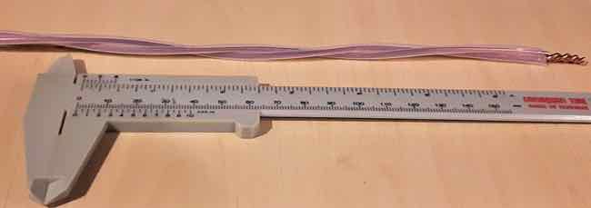
I selected a PTFE Tubing with Internal Dia that is 25% - 30% larger than
the diameter of the bare wire will suffice
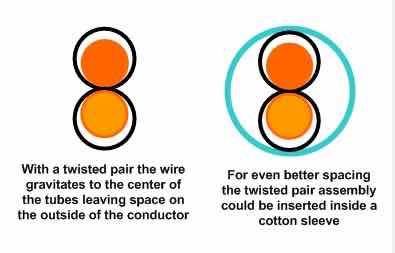
If you consider the cross section of a Live/Signal conductor of a cable, the twisted pair. it is quite clear that provided the tube does not collapse there is only ever ONE point of contact with the teflon tube, with lots of air around the actual wire
This is the value Teflon has over Cotton and Silk sleeves, because cotton and silk tends to collapse around the wire resulting in multiple points of contact, increasing the value of the DK
Unfortunately, the UP-OCC copper I have been using from both Neotech and VH Audio both have insulation that must first be removed
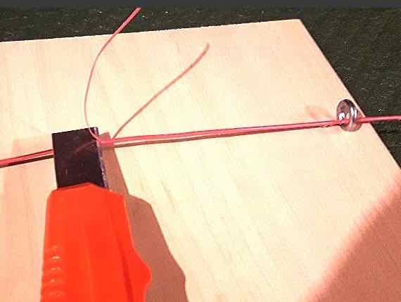
In order to remove the insulation with a minimum of effort I inserted an eye ring in the end of a piece of wood (see below) to make a simple striping jig
The rest of this process depicts how to fabricate the Signal conductor for the Helix interconnect
FOR the 2 x 18 gauge Interconnect SIGNAL CONDUCTOR
AND the 2 x 16 gauge Source Power Cables LIVE CONDUCTOR
AND the 2 x 16 gauge Speaker Cable SIGNAL CONDUCTOR
AND the 2 x 14 gauge (heavy duty) HD Power Cables LIVE CONDUCTOR
Strip the insulation from the two wires (as shown above) and twist one end tightly to hold the wires together
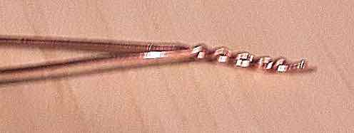
insert each wire into it's own Teflon tube and then gently twist as shown below
i.e. approximately 1 complete twist every 4" (10cm)
Then tightly twist the other end of the conductor the same as shown above
For all cable types,
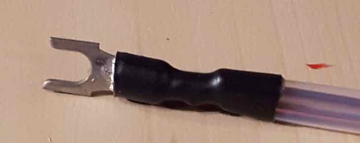
The Power Cable LIVE conductor is terminated with a spade and both tubes are sealed with a single piece of Heat Shrink as show below.
Only attach the spade at one end to allow for easy insertion into the Helix Coil and then attach the spade to the other end and seal the end
Using this technique, a view of a cross section of the twisted pair conductor reveals…
An additional benefit for the longer cables, such as speaker cables…
If desired, the conductor assembly can be placed inside a cotton sleeve for improved vibration control, but it is NOT required
So why prevent air flow?
I was initially very concerned about oxidation because if it was a real issue it meant people would be faced with re-wiring their cables once they turn green.
In recognition of the superb performance achieved by applying this technique I have decided to name this version of the HELIX cables…
Speaker Cable...
Power Cable...
- strange as it may seem, you DO NOT have to apply this insulation guide to the Neutral wire
Links to the pages on how to build the individual cables can be found at the bottom this page
So How do you build a conductor that has Air as the dielectric?
Teflon tube has been a long time favourite in my cables (early on) so I looked back a previous versions of the cables and realized if I used the right sized tube it would allow enough air around the wire and result in a very small area of contact.
I selected a PTFE Tubing with Internal Dia that is 25% - 30% larger than
the diameter of the bare wire will suffice
If you consider the cross section of a Live/Signal conductor of a cable, the twisted pair. it is quite clear that provided the tube does not collapse there is only ever ONE point of contact with the teflon tube, with lots of air around the actual wire
This is the value Teflon has over Cotton and Silk sleeves, because cotton and silk tends to collapse around the wire resulting in multiple points of contact, increasing the value of the DK
Unfortunately, the UP-OCC copper I have been using from both Neotech and VH Audio both have insulation that must first be removed
- but bare UP-OCC wire can be purchased from retailers, such as Part Connexion
In order to remove the insulation with a minimum of effort I inserted an eye ring in the end of a piece of wood (see below) to make a simple striping jig
- Thread the wire through the eye ring
- hold the wire on the board at the other end of the board
- Place the blade of a utility knife on the wire and lift the blade to about a 5 degree angle
- and simply cut a small sliver of insulation from the wire
- then peel the insulation from the wire
The rest of this process depicts how to fabricate the Signal conductor for the Helix interconnect
- which uses 2 x 18 gauge wires
- but the same process can be applied to any HELIX IMAGE (Air) Cable
FOR the 2 x 18 gauge Interconnect SIGNAL CONDUCTOR
AND the 2 x 16 gauge Source Power Cables LIVE CONDUCTOR
AND the 2 x 16 gauge Speaker Cable SIGNAL CONDUCTOR
AND the 2 x 14 gauge (heavy duty) HD Power Cables LIVE CONDUCTOR
Strip the insulation from the two wires (as shown above) and twist one end tightly to hold the wires together
insert each wire into it's own Teflon tube and then gently twist as shown below
i.e. approximately 1 complete twist every 4" (10cm)
Then tightly twist the other end of the conductor the same as shown above
For all cable types,
- apply a thin coat of solder (i.e. TIN) to the tightly twisted portions at both ends
- trim to the appropriate length for the type of connector to be used
- seal the ends of the tubes with either hot glue or Heat Shrink tubing (my preference)
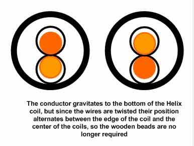
- Insert the conductor into the Helix coil
- solder to the appropriate connector at each end
The Power Cable LIVE conductor is terminated with a spade and both tubes are sealed with a single piece of Heat Shrink as show below.
Only attach the spade at one end to allow for easy insertion into the Helix Coil and then attach the spade to the other end and seal the end
Using this technique, a view of a cross section of the twisted pair conductor reveals…
An additional benefit for the longer cables, such as speaker cables…
If desired, the conductor assembly can be placed inside a cotton sleeve for improved vibration control, but it is NOT required
So why prevent air flow?
- In order to prevent the bare copper wire (or silver) from oxidizing
- Initially some oxidation will occur and a little dullness will result
- but based on my current speaker cables which have been in place for about 4 months, the dulling of the copper appears to have stopped
I was initially very concerned about oxidation because if it was a real issue it meant people would be faced with re-wiring their cables once they turn green.
- But on thinking about the oxidation process further, those copper weather veins on buildings generally take about 5 - 7 years to obtain the green patina
- they are open to the elements 24/7.
- Also, the bare ground wire in my house (that connects to the water supply) is still pretty bright after 4 years
- I have had a piece of bare wire sitting on my rack for about 8 months and it has tarnished, but the bare wire inside the tubes is still as bright as the day they were made
In recognition of the superb performance achieved by applying this technique I have decided to name this version of the HELIX cables…
The HELIX IMAGE (Air)
When this approach is used on all Helix cables the results are stunning !!!
This technique can be applied to any of the following HELIX IMAGE Cables…
Interconnect Cable...
Speaker Cable...
Power Cable...