


DIY Power Cables - The "HELIX IMAGE" Power Cable
I started looking at cable architectures a while back, initiated by an experience with a home lighting repair.
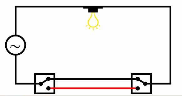
I was installing a new two way switch on a hallway light, the type with a switch at each end of the hallway (see diagram below). I decided to play it safe and use my multimeter to verify the open/closed position of the switches.
With the switch in the OFF position everything checked out, but with the switch in the ON position I found that there was a reading of 42 volts on what was supposed to be the "dead conductor" i.e. the red conductor in the diagram below.
I subsequently found articles on the web which verified that in this particular situation it is common for one of the conductors in standard household power cable to register an "induced voltage".
In the case of “conventional” power cable architectures, the live conductor and the neutral conductor tend to be side by side in extremely close proximity for the length of the cable, so is it reasonable to assume that noise will be induced between the conductors in a power cable?.
Would “noise pollution” also be present on the ground conductor, which, and depending on the design of a components circuit, might also have an adverse effect on sound quality?
Additional research revealed even more to consider regarding good cable design...
For more information on cable design issues please read the three articles below that talk about the many problems that challenge cables designers.
They will provide a great deal of insight into the many parameters and design techniques employed to build cables that excellent in their performance.
The articles are specific to Interconnect and speaker cables, but much of the theory also applies to power cables
https://www.psaudio.com/article/cables-time-is-of-the-essence-part-1/
https://www.psaudio.com/article/cables-time-is-of-the-essence-part-2/
https://www.psaudio.com/article/cables-time-is-of-the-essence-part-3/
The premise of the helical design concept eliminates the parallel conductors which minimizes cable issues to imperceivable levels!
BONUS! - the Helix acts as a Faraday Cage just for the signal wire!
But First My Disclaimer:
DO NOT attempt any of the assemblies detailed below unless you are an experienced Electrical Professional OR Electronics Hobbyist - otherwise consult a technician!
YOU ARE RESPONSIBLE: for following local electrical codes. Failure to do so may result in personal injury, damage to equipment, or power cable failure which can result in fire.
YOU ARE RESPONSIBLE: for ensuring the cable selected is suitably rated for the power requirements of the component(s) it will be attached too !
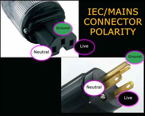
YOU ARE RESPONSIBLE: for ensuring the IEC/Mains connectors are installed observing the correct polarity !
- failure to do so can result in poor operation, component failure or electric shock.
YOU ARE RESPONSIBLE: for ensuring the dielectric strength of the insulation on ALL conductors used, meets or exceeds local codes!
e.g. In North America - 600v at 200 Celsius for 120v 50/60 Hz supply
These Power cables are only to be used for Home Audio Purposes and must not subjected to harsh environments and frequent handling, which generally require additional protective coverings.
The materials mentioned below comply with most codes for NORTH AMERICA ONLY!
Electrical codes in other countries may require the selection of different materials, therefore YOU ARE RESPONSIBLE for following those local electrical codes.
YOU are responsible for ensuring “power related” assemblies are safe to use!
So what’s changed???
Since there is very little actual difference from a geometry perspective between the previous versions of the power cable and this renamed version I considered not assigning a new name, but then I realized
- the expandable sleeve over the cable assembly has been removed
- the expandable sleeve on the Live Wire has been removed
- a new Live Conductor option is now used, which improves the resolution performance of the system components
Why remove the sleeve?
The nylon sleeve and heat shrink increases the Dielectric Constant (D.C.), which impedes cable performance
- If you prefer to use a sleeve I would recommend a Cotton Sleeve over the man made fibres
And so the Power Cable inherits the HELIX IMAGE nomenclature !
What size wire do you recommend for various components?
I have found that using a 12 gauge live Conductor built from four 18 gauge solid copper wires will suffice for the most demanding components (e.g. amps up to 600 watts).
You might think a 12 Gauge cable is capable of handling much more that 600 watts, HOWEVER, transient peaks in the music can result in very high instantaneous current demands. This cable has been designed to accommodate a significant amount of "headroom" in order to handle those peaks without compressing the signal, so I conservatively rate its use up to 600 watts.
However, since you will NEVER drive a high output amps to their max, these power cables can be used with higher wattage components up to 1000 watts.
For Source components up to 40 watts I have added construction details further down this page that uses an 18 gauge solid silver wire that provides exceptional performance, But after some testing using the 18 Gauge Solid Copper it would appear that the copper performs equally as well.
You can use 18 gauge wire for most lower powered Source Components up to 40 watts with additional cotton sleeve as detailed below.
If you component draws between 40-80 watts, then use two strands of 18 gauge wire/
Materials...
The materials listed below will build a 5ft power cable that is suitable for use with Power Aimplifiers rated up to 600 watts.
- LIVE Conductor: Either…
- One single strand of 12 gauge Neotech UP-OCC solid copper (my preference) or…
- 4 strands of 18 gauge OCC Solid Copper with AirLok insulation for a more relaxed presentation
- However, if you want a more budget oriented power cable you can use either
- 12 gauge Duelund wire with the Polymer insulation (NOT the Cotton/Oil insulation)
- OR 12 gauge Mil-spec wire from Take Five audio
- NEUTRAL Conductor: 30 feet of stranded Mil Spec 12 AWG Silver Plated Copper Wire, Cryo Treated, Red - available from Take Five Audio (TFA)
- GROUND Conductor: 15 feet of green 12 gauge mains copper wire from Home Depot
- 4" of 3/4" or 1” black Heat Shrink sleeve
- 2" of 1/8" black heat shrink sleeve with adhesive
- 6 ft of 1/8" diameter cotton sleeve - when installed the sleeve expands, which makes it shorter
- 1 Pair of SONAR QUEST CRYO Ag Audio Grade Silver plated IEC plug + US main plug
- eutectic solder suited for electronics use - or WBT 4% silver solder can also be used
- 6 x 10-12 gauge copper spade/fork connectors
- For Spade/Fork terminals take look at the Grainger Web site and in their options check box select TERMINAL TYPE: Standard, WIRE RANGE: 12-10 gauge, INSULATION TYPE: Bare and SEAM: Butted
- Fork Terminals - Spade Terminals - Grainger Industrial Supply
- 1 - 5/16” (7-8mm) diameter fibreglass rod 4-5 ft long - available from Home Depot
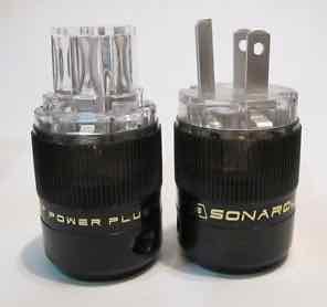
The Sonar Quest connectors have heavy Silver plating on pure copper contacts that provide excellent clamping and transmission of electrical current - available from ebay
I use an approximate ratio of 3:1 of Ground/Neutral:Live conductor
e.g. for a 5ft power cable I use 15ft of Ground and 30ft of Neutral Conductor
How To Make Them...
To determine the “Direction” of the Helix - see Inside The Helix Geometry.
The Neutral Conductor...
The Neutral Conductor is made from two lengths of the Mil Spec 12 AWG Silver Plated Copper Wire listed above.
Why two pieces? - this effectively make the neutral wire a 9 gauge conductor, which I have found performs much better than a single 12 gauge wire, resulting in faster dynamics, better bass performance and control and more natural imaging.
Cut the 30 ft length of wire into two equal length pieces.
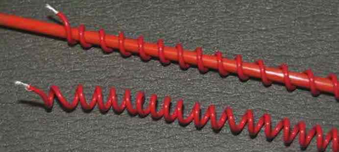
On the 5/16” rod, wind the neutral conductor in a helix configuration, space the windings about 1/4” apart and remove from the rod.
Repeat the winding process with the second piece of wire.
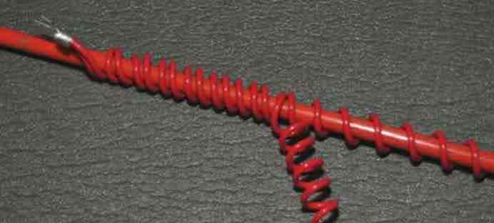
With the second coil of wire still on the rod...
- Attach the first coil to the second coil with a 10 gauge spade connector
- Wind the first “coil” of wire between its windings as shown below
Remove the two “intertwined” coils from the rod
The Ground Conductor...
On the 5/16" rod, wind the green GOUND conductor in a helix configuration, space the windings about 1/4” apart and remove from the rod.
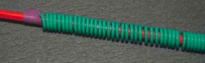
Then place the two red conductors back on the rod and add the coiled ground wire just as you did the second neutral conductor (above)
The Live Conductor…
For heavier current applications, like amps, power distribution panels and extension cables (up to 600 watts) I now use one strand of 12 gauge Neotech UP-OCC solid copper with Teflon insulation. Please note that this wire is very stiff and as such it should NOT be used for power cables that are flexed frequently.
For a more "mellow" presentation you could use 4 strands of 18 gauge solid OCC copper from VH Audio.
If you feel you need higher current carrying capacity, just add another strand of the VH Audio wire
To fabricate the live conductor using 4 strands of VH Audio Solid copper…
- First, cut 4 pieces of wire to the length you require + 1" to allow for trimming
- strip 3/4" (15mm) of insulation from each wire
- twist together tightly using pliers
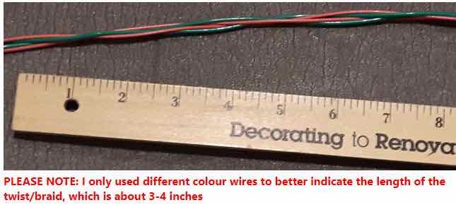
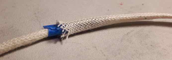
- then braid the 4 wires in a "relaxed braid" as shown in the photo below
- when you get to the end of the braid, strip 3/4" (15mm) of the insulation and twist the 4 wires tightly together
- insert the braided wires into the cotton sleeve and secure each end with a piece of Heat Shrink
Here is a photo to show the "relaxed braid" I currently use.
Using a relaxed braid allows the cable assembly to flex more easily
Regardless of which wire you select for the live conductor
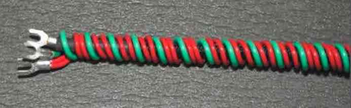
- Trim one end of the "conductor assembly" to the length of the spade terminal collar
- Attach a 12/10 awg spade connector on one end of the Live conductor assembly, crimp and solder in place.
- Thread the Live conductor assembly through the centre of the red & green coil(s)
- Trim and attach a second 12/10 awg spade connector on free end of the Live conductor, crimp and solder in place.
- Attach a second 12/10 awg spade connector on the two free ends of the neutral conductor, crimp and solder in place.
- Place 12/10 awg spade connectors on both ends of the ground conductor, crimp and solder in place
Cut two adequate lengths of 3//4" or 1” heat shrink tubing and place over each end of the cable assembly to provide a surface for the plug clamp on to.
Here are two of my power cables positioned on cable lifters...
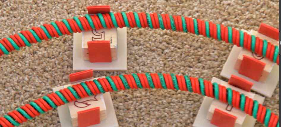
NOTE: When Attaching the Sonar Quest connectors to the cable assembly...
PLEASE ensure you adopt the correct polarity - your life may depend on it!!!
Assembly Notes...
Why do I use spade connectors? -
- First, trying to attach the mains/IEC connectors to a large gauge cable is very difficult,
- More importantly - the spade connectors prevent detachment from the connectors in the event of unforeseen stress being placed on the connectors.
- I have also found that the spade connectors that are crimped and soldered actually improve sound quality.
For a more secure crimped joint, I always crimp from the back - as shown in the image below, which prevents the collar from opening.
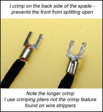
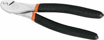
I use pliers as shown in this image that applies an extended crimp along the whole length of the spade connectors collar
Cables that are more suited to source components can use lighter gauge conductors, but be sure to determine their power requirements and select a gauge that can handle it with headroom to spare.
Can you use other brands of IEC/Mains connectors?
Of course. Some people might prefer to use Furutech, or Oyaide high quality connectors.
Others may prefer to use something more reasonably price, like the Vanguard range of connectors.
I believe the Sonar Quest connector line provides exceptional sound quality for a reasonable price.
Power Cables for my Source Components...
Most “Source components” - like CD players, phono stages, DACs, etc.. draws significantly less power than amplifiers. They typically consume up to 40 watts
So, they do not require a 12 gauge power cable !
Most source components have a “less capable” power supply than amplifiers.
So their performance can be improved using a better “quality” power cable !
The following are details for building the HELIX IMAGE - SOURCE power cable as follows...
- The dual neutral wire is dual 14 gauge silver plated Mil-spec wire
- The ground wire is a single 14 gauge copper wire - I now use the Mil-spec wire - it retains the coil shape
- for neutral and ground wires - use a ratio of 4:1 neutral to signal to provide adequate helix coverage
- The Live conductor can be either an 18 gauge OCC solid silver wire from VH Audio - with AirLok mains insulation rated at 600v, or the more affordable 18 gauge Solid Copper wire with AirLok Insulation. If you are uncertain about the amount of power consumed by your component you can opt to use two strands of wire for the live conductor.
- NOTE: I have now tested both Silver and Copper wires with AirLok insulation on one of my source components and I could not tell the difference between the two. However, higher resolving components "may" provide slightly better results using the solid silver wire.
- you will also need cotton sleeve to space the live conductor more evenly within the Helix coil
First - the 18 gauge Solid Silver, or Solid Copper wire with the AirLok insulation can be purchased from VH Audio...
https://www.vhaudio.com/unicrystal-occ-silver-wire.html
https://www.vhaudio.com/unicrystal-occ-copper-wire.html
NOTES:
- The AirLok insulation of this wire is rated at 600V and has a lower Dielectric Constant than Teflon
- DO NOT use wire with cotton insulation - they are not rated for mains use in power cables
So - for a 5 ft cable you will need...
- 2 x 20 ft of 14 gauge Silver plated Mil-spec wire from Take Five audio for the neutral
- 1 x 20 ft of 14 gauge Silver plated Mil-spec wire from Take Five audio for the Ground
- 5 ft of UniCrystal OCC .99999 Silver Wire - AirLok Insulation from VH Audio (or the Solid Copper variant)
- 11 ft of 1/8” cotton sleeve
- 14 and 18 gauge Spade connectors - auto supply stores normally have very cheap spade connectors
- 2" of 1/8” heat shrink tube with adhesive
- some masking tape
- quality solder - I now use eutectic solder, but high content (e.g. 4%) silver solder can also be used
Follow the instructions above for creating the neutral and ground helix coils
The LIVE wire takes a little more effort...
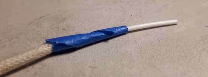
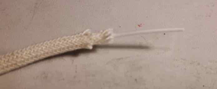
Cut the cotton sleeve one inch shorter than the live wire and thread onto the wire
Using a small piece of masking tape, secure the cotton sleeve to the wire
Thread the second layer of cotton sleeve over the first layer
- this is more difficult, because you can only thread about 1” at a time
Note: the length of the second layer of Cotton sleeve expands, so a slightly longer length is required
Once complete REMOVE the masking tape !
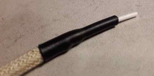
Both ends should look like this...
Cut a 3/4” length of the Heat Shrink (with adhesive) and stretch one end, using a pair of needle nose pliers
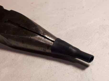
Place the heat shrink over the double layer of cotton sleeve
Apply heat to secure the cotton sleeve to the wire with the heat shrink
- try NOT to burn the cotton sleeve
Thread the live conductor into the Helix neutral and ground assembly and attach the spade connectors to each end
Attach the mains connectors and you are DONE!
So why do they work?
The power supply of an amplifier tends to be very well designed and built, because of the power requirements at play, whereas the more affordable source components, tend to be built to a price point and therefore the power supply is very often not as “capable” as the rest of the circuit.
The rest of the electrical components are very often just as capable as those in the amp, but in operation, their performance is impacted by the inadequacies of the power supply when handling transient peaks in the signal
So if you use a very good power cable on a source component you can mitigate some of the inadequacies of its power supply.
The solid silver wire used for the Live conductor has an IACS rating of around 106% compared to copper at 100%
What is IACS? — it’s a measure of the conductivity of various metals relative to “Pure Copper”, a standard developed for copper wire producers, annealed copper having a rating of 100%
So the silver wire in these cables is able to respond more quickly to transient signal demands.
ALSO - the insulation on this particular silver wire has a dielectric constant (D.C.) of 1.4, compared to Teflon at 2.1.
The continual change in polarity of the alternating current charges and recharges the insulation much like the dielectric in a capacitor, which induces noise into the conductor. A lower D.C. reduces the amount of noise generated internally within the conductor itself.
However, solid silver wire is very expensive, and I am a frugal being, which is why I have only selected it for power cables that will be used only on my source components.
But you could use multiple strands of the solid silver wire for the live conductor to increase the current handling capability - e.g. 4 x 18 gauge strands would equate to a 12 gauge conductor
What improvements did I observe?
- There was a significant improvement in the details of “venue acoustics” - i.e. echoes and reverberations
- dynamics were noticeably crisper
- the image was noticeably larger front-to-back and there was more precision of artist location within the image
- there appeared to be more “air” around each performer
- clarity was improved, i.e. you could hear more of the fine details and layers within the music
I recommend making the single 18 gauge cables...
ONLY - if your component draws less than 40 watts - WHY?
The 18 gauge wire(s) is rated at around 1 amp - HOWEVER - transient spikes can result in significantly higher current draws, which can impact performance or even overheat the cable.
For components rated BETWEEN 40 - 80 watts - use 2 x 18 gauge strands (effectively 15 gauge).
FOR USE WITH AMPLIFIERS - you could use 4 X 18 gauge wire for the live conductor - that would effectively make it 12 gauge conductor.
Can I just Upgrade an existing 12 gauge HELIX Power Cable?
Yes - just replace the 12 gauge Live conductor with a single 18 gauge conductor
- HOWEVER - mark the cable in some way to identify that it has the small gauge live wire that is NOT suitable for amplifiers
NOTE: The 12 gauge wire used for the neutral and ground wire when upgrading a 12 gauge power cable in this manner, is NOT detrimental to cable performance if using the 18 gauge live conductor.
Using Helix Power Cables in a more "Demanding" Environment
Let's face it, power cables in an audio system "generally" sit at the back of the audio rack and DO NOT move, except for the occasional component swap or audition. It's not what I consider a dynamic environment. so the construction methods and materials above are "safe", but for this style of use ONLY!
But, if you are planning on using a HELIX power cable for other purposes, e.g. I use them on my guitar amps, then I would highly recommend adopting the following "adjustments" to the Helix designs above...
- ONLY USE Duelund 12 gauge with the PolyCAST insulation for the LIVE conductor - it can withstand much more flexing of the cable than the Solid Core wires recommended above.
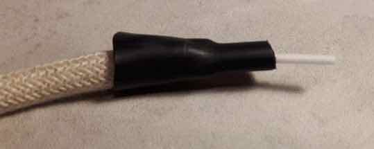
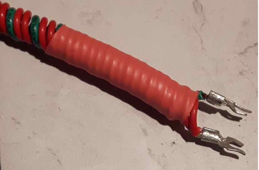
- Ensure that the Neutral and Ground Helix Coils are held in place at each end of the cable with two inches of Heat-shrink (with adhesive) as in the image below
- Also, use an expandable Nylon Sleeve to protect the cable assembly from abrasions and secure at each end with a piece of Heat-shrink (with adhesive)
- Ensure the cable clamps on the connector plugs securely hold the cable in place
I use this style of cable on my guitar amps and I cannot tell the difference between the 12 gauge Duelund and the 4 x 18 gauge Solid Copper versions of the Helix Power Cable.
I will warn that even this version of the Helix power cable IS NOT SUITED (intended or designed) to be used in extreme rugged and demanding environments. such as a recording studio or a live performance ! However exercising a little care and performing regular inspections to assess whether damage has occurred, you can use this variant in an the more demanding environment such as this.
If you need a "REALLY HEAVY DUTY CABLE", then, The Helix IS NOT the cable you need, so get yourself a length of Furutech bulk mains cable, which is designed to be used in almost any environment.
The Journey...
I’m a frugal person with a distinct dislike of overpaying for something as simple as a piece of wire!
I started making my own cables many years ago from Bulk cable with reasonably priced connectors.
I first tried Furutech bulk cable and then stumbled upon DH Labs, which I believe offers similar performance for about 1/3 the price - how could you not like that.
I then investigated a braided architecture which proved very effective, even using plain old Romex house wire.
Finally, I tried the Helix Architecture, which has proved to be the best performing power cable architecture to date.
I have now implemented this architecture on all my cables that have anything to do with audio.
What do they sound like?
The “HELIX IMAGE Power Cable” is a high performance power cable that allows connected components to perform to the best of their abilities.
They assist components in delivering ultra fast dynamic performance, exceptional clarity, expansive imaging and a very deep and exceptionally well controlled and very natural bass performance.
How Long is the Burn-In Period?
It is imperative that these cables are allowed adequate time to settle and burn-in...
- they will sound extremely good on initial installation
- after about 60 hours they allow more of the micro details in the form of venue specific reverberation captured in live recordings, or applied by very talented sound engineers, to clearly be heard.
The end of the Road?
My hope is that this design will be embraced and enhanced by the DIY Community and encourage them to experiment with different conductor materials and configurations to tailor the sound to their own liking.
For Helix cable spec’s please see Its More Than Just Numbers - Isn't It?
My Review System:
Custom built turntable with a Soundsmith Denon DL103 phono cartridge mounted on an Audiomods Arm with one piece silver litz harness + KLEI Absolute®Harmony RCA’s
Simaudio MOON LP5.3 RS phono stage
Bluesound Node 2i music server
Bryston B135 Integrated amp.
Gershman Acoustics Sonogram speakers.
 Give them a try - and - Enjoy The Music!
 ![]()