


DIY Power Cables - The "HELIX IMAGE" Power Cable
I started looking at cable architectures a while back, initiated by an experience with a home lighting repair.
I was installing a new two way switch on a hallway light, the type with a switch at each end of the hallway (see diagram below). I decided to play it safe and use my multimeter to verify the open/closed position of the switches.
With the switch in the OFF position everything checked out, but with the switch in the ON position I found that there was a reading of 42 volts on what was supposed to be the "dead conductor" i.e. the red conductor in the diagram below.
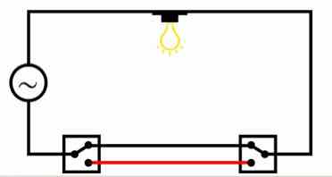
I subsequently found articles on the web which verified that in this particular situation it is common for one of the conductors in standard household power cable to register an "induced voltage".
In the case of “conventional” power cable architectures, the live conductor and the neutral conductor tend to be side by side in extremely close proximity for the length of the cable, so is it reasonable to assume that noise will be induced between the conductors in a power cable?.
Would “noise pollution” also be present on the ground conductor, which, and depending on the design of a components circuit, might also have an adverse effect on sound quality?
Additional research revealed even more to consider regarding good cable design...
For more information on cable design issues please read the three articles below that talk about the many problems that challenge cables designers.
They will provide a great deal of insight into the many parameters and design techniques employed to build cables that excellent in their performance.
The articles are specific to Interconnect and speaker cables, but much of the theory also applies to power cables
https://www.psaudio.com/article/cables-time-is-of-the-essence-part-1/
https://www.psaudio.com/article/cables-time-is-of-the-essence-part-2/
https://www.psaudio.com/article/cables-time-is-of-the-essence-part-3/
The premise of the helical design concept eliminates the parallel conductors which minimizes cable issues to imperceivable levels!
BONUS! - the Helix acts as a Faraday Cage just for the signal wire!
But First My Disclaimer:
DO NOT attempt any of the assemblies detailed below unless you are an experienced Electrical Professional OR Electronics Hobbyist - otherwise consult a technician!
YOU ARE RESPONSIBLE: for following local electrical codes. Failure to do so may result in personal injury, damage to equipment, or power cable failure which can result in fire.
YOU ARE RESPONSIBLE: for ensuring the cable selected is suitably rated for the power requirements of the component(s) it will be attached too !
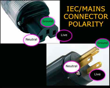
YOU ARE RESPONSIBLE: for ensuring the IEC/Mains connectors are installed observing the correct polarity !
- failure to do so can result in poor operation, component failure or electric shock.
YOU ARE RESPONSIBLE: for ensuring the dielectric strength of the insulation on ALL conductors used, meets or exceeds local codes!
e.g. In North America - 600v at 200 Celsius for 120v 50/60 Hz supply
These Power cables are only to be used for Home Audio Purposes and must not subjected to harsh environments and frequent handling, which generally require additional protective coverings.
The materials mentioned below comply with most codes for NORTH AMERICA ONLY!
Electrical codes in other countries may require the selection of different materials, therefore YOU ARE RESPONSIBLE for following those local electrical codes.
YOU are responsible for ensuring “power related” assemblies are safe to use!
So what’s changed???
Since there is very little actual difference from a geometry perspective between the previous versions of the power cable and this renamed version I considered not assigning a new name, but then I realized
- The Helix neutral has a larger diameter
- the expandable sleeve over the cable assembly has been removed
- the expandable sleeve on the Live Wire has been removed
Why remove the sleeve?
The nylon sleeve and heat shrink increases the Dielectric Constant (D.C.), which impedes cable performance
The only design element present in the other HELIX IMAGE cables which helps reduce D.C that has not been applied are the wood beads to centre the live wire in the helix.
As it turns out, removing the expandable sleeve, all of the heat shrink sleeve and increasing the diameter of the helix, seems to have elevated the performance of the power cable to similar levels of performance as the other HELIX IMAGE cables
And so the Power Cable inherits the HELIX IMAGE nomenclature !
What size wire do you recommend for various components?
I have found that using the 12 gauge Duelund wire will suffice for the most demanding components (e.g. amps up to 600 watts).
For Source components up to 40 watts I have constructions details further down this page that uses an 18 gauge solid silver wire that provides exceptional performance.
You can use 16 gauge Duelund wire for most lower powered Source Components up to 60 watts with additional cotton sleeve as detailed below for the Solid Silver live conductor.
IF you have very powerful amplifiers (ie. in excess of 600 watts) and you are also using low impedance speakers (e.g. 2-4 Ohms) you may want to consider using...
- 2 x12 gauge (i.e. 9 gauge equivalent) Duelund wires for the live wire and
- 3 x 12 gauge Mil-spec wires for the neutral
Materials...
The materials listed below will build a 5ft power cable that is suitable for use with Power Aimplifiers rated up to 600 watts.
- LIVE Conductor: Duelund stranded 12 gauge wire with Polycast insulation
- However, if you want a more budget oriented power cable you can use 12 gauge Mil-spec wire from Take Five audio
- NEUTRAL Conductor: 30 feet of stranded Mil Spec 12 AWG Silver Plated Copper Wire, Cryo Treated, Red - available from Take Five Audio (TFA)
- GROUND Conductor: 15 feet of green 12 gauge mains copper wire from Home Depot
- 2 feet of 1” black Heat Shrink sleeve
- 1 Pair of SONAR QUEST CRYO Ag Audio Grade Silver plated IEC plug + US main plug
- eutectic solder suited for electronics use - or WBT 4% silver solder can also be used
- 10-12 gauge copper spade/fork connectors
- For Spade/Fork terminals take look at the Grainger Web site and in their options check box select TERMINAL TYPE: Standard, WIRE RANGE: 12-10 gauge, INSULATION TYPE: Bare and SEAM: Butted
- Fork Terminals - Spade Terminals - Grainger Industrial Supply
- 1 5ft x 3/8”(10mm) or 1/2” (12.5 mm) fibreglass rod - available from Home Depot

The Sonar Quest connectors have heavy Silver plating on pure copper contacts that provide excellent clamping and transmission of electrical current - available from ebay
I use an approximate ratio of 3:1 of Ground/Neutral:Live conductor
e.g. for a 5ft power cable I use 15ft of Ground and 30ft of Neutral Conductor
How To Make Them...
To determine the “Direction” of the Helix - see Inside The Helix Geometry.
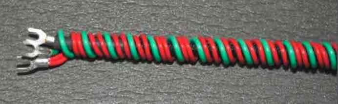
The Neutral Conductor...
The Neutral Conductor is made from two lengths of the Mil Spec 12 AWG Silver Plated Copper Wire listed above.
Why two pieces? - this effectively make the neutral wire a 9 awg conductor, which I have found performs much better than a single 12 gauge wire, resulting in faster dynamics, better bass performance and control and more natural imaging.
Cut the 30 ft length of wire into two equal length pieces.
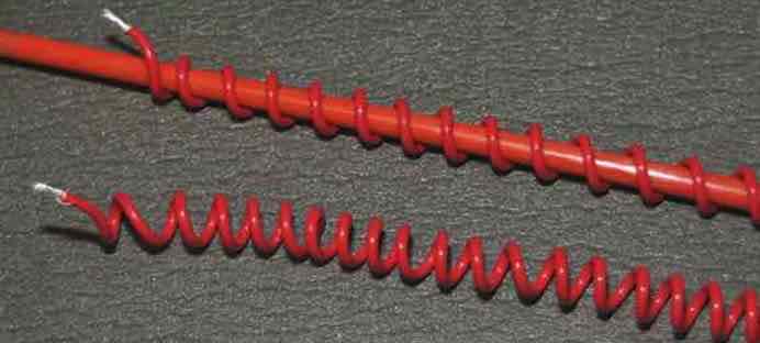
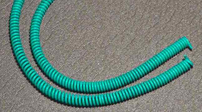
On the 3/8” or 1/2” rod, wind the neutral conductor in a helix configuration, space the windings about 1/4” apart and remove from the rod.
Repeat the winding process with the second piece of wire.
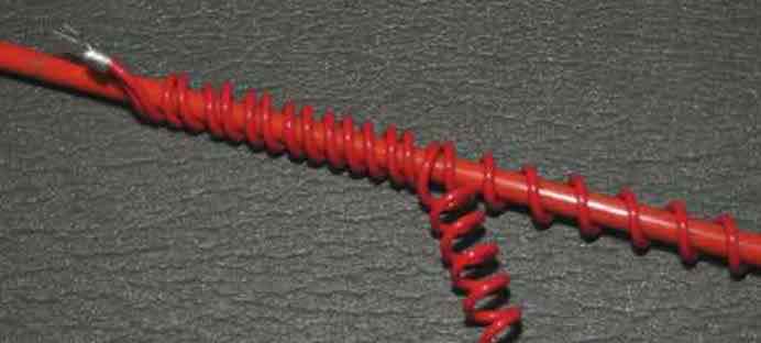
With the second coil of wire still on the rod...
- Attach the first coil to the second coil with a 10 gauge spade connector
- Wind the first “coil” of wire between its windings as shown below
Remove the two “intertwined” coils from the rod
The Ground Conductor...
On the 3/8” or 1/2” rod, wind the green GOUND conductor in a helix configuration, space the windings about 1/4” apart and remove from the rod.
Attach a 12/10 awg spade connector on one end of the Live conductor, crimp and solder in place.
Thread the Live conductor through the centre of the red coil(s)
Attach a second 12/10 awg spade connector on free end of the Live conductor, crimp and solder in place.
Attach a second 12/10 awg spade connector on the two free ends of the neutral conductor, crimp and solder in place.
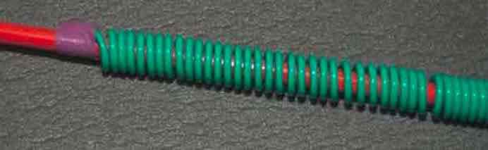
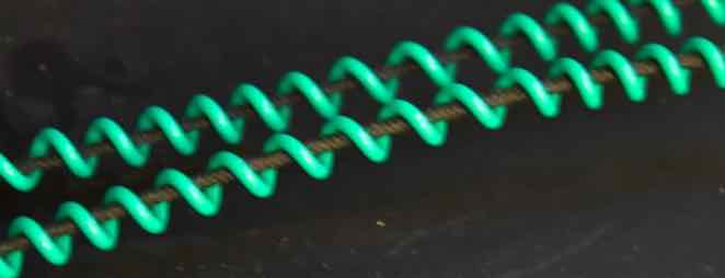
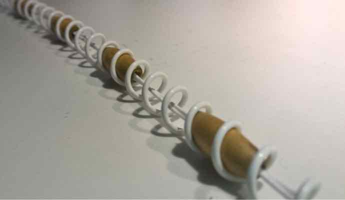
Wind the green wire between the “double winding” of the neutral conductor as shown below.
Place 12/10 awg spade connectors on both ends of the ground conductor, crimp and solder in place
Cut two adequate lengths of 1” heat shrink tubing and place over each end of the cable assembly to provide a surface for the plug clamp
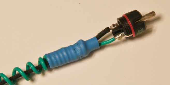
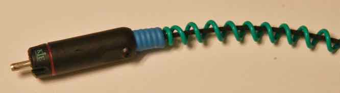
Here are two of my power cables positioned on cable lifters...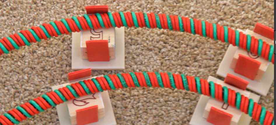
NOTE: When Attaching the Sonar Quest connectors to the cable assembly...
PLEASE ensure you adopt the correct polarity - your life may depend on it!!!
Assembly Notes...
Why do I use spade connectors? -
- First, trying to attach the mains/IEC connectors to a large gauge cable is very difficult,
- More importantly - the spade connectors prevent detachment from the connectors in the event of unforeseen stress being placed on the connectors.
- I have also found that the spade connectors that are crimped and soldered actually improve sound quality.
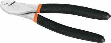
For a more secure crimped joint, I always crimp from the back - as shown in the image below, which prevents the collar from opening.
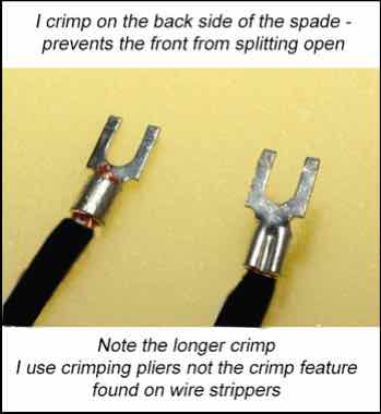
I use pliers as shown in this image that applies an extended crimp along the whole length of the spade connectors collar
Cables that are more suited to source components can use lighter gauge conductors, but be sure to determine their power requirements and select a gauge that can handle it with headroom to spare.
Can you use other brands of IEC/Mains connectors?
Of course. Some people might prefer to use Furutech, or Oyaide high quality connectors.
Others may prefer to use something more reasonably price, like the Vanguard range of connectors.
I believe the Sonar Quest connector line provides exceptional sound quality for a reasonable price.
Power Cables for my Source Components...
Most “Source components” - like CD players, phono stages, DACs, etc.. draws significantly less power than amplifiers. They typically consume up to 40 watts
So, they do not require a 12 gauge power cable !
Most source components have a “less capable” power supply than amplifiers.
So their performance can be improved using a better “quality” power cable !
The following are details for building the HELIX IMAGE - SOURCE power cable as follows...
- The neutral wire is dual 14 gauge silver plated Mil-spec wire
- The ground wire is a single 14 gauge copper wire - I now use the Mil-spec wire - it retains the coil shape
- for neutral and ground wires - use a ratio of 4:1 neutral to signal to provide adequate helix coverage
- The Live conductor is an 18 gauge solid silver wire from VH Audio - with mains insulation, i.e. 600v
- you will also need cotton sleeve to space the live conductor evenly within the Helix coil
First - the 18 gauge Solid Silver wire with the AirLok insulation can be purchased from VH Audio...
https://www.vhaudio.com/unicrystal-occ-silver-wire.html?gclid=EAIaIQobChMI-JqsneOm6AIVzP_jBx0yAw1IEAAYASAAEgIRovD_BwE
NOTES:
- The AirLok insulation of this wire is rated at 600V and has a lower Dielectric Constant than Teflon
- DO NOT use wire with cotton insulation - they are not rated for mains use in power cables
So - for a 5 ft cable you will need...
- 2 x 20 ft of 14 gauge Silver plated Mil-spec wire from Take Five audio
- 1 x 20 ft of 14 gauge Silver plated Mil-spec wire from Take Five audio
- 5 ft of UniCrystal OCC .99999 Silver Wire - AirLok Insulation
- 11 ft of 1/8” cotton sleeve
- 14 and 18 gauge Spade connectors - auto supply stores normally have very cheap spade connectors
- a small length of 1/8” heat shrink tube with adhesive
- some masking tape
- quality solder - I now use eutectic solder, but high content (e.g. 4%) silver solder can also be used
Follow the instructions above for creating the neutral and ground helix coils
The LIVE wire takes a little morw effort...
Cut the cotton sleeve one inch shorter than the live wire and thread onto the wire
Using a small piece of masking tape, secure the cotton sleeve to the wire
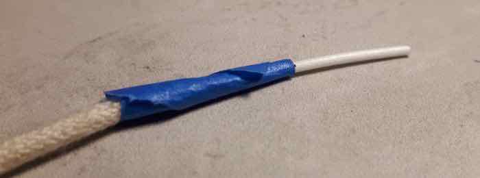
Thread the second layer of cotton sleeve over the first layer
- this is more difficult, but only thread about 1” at a time
Note: the length of the second layer of Cotton sleeve expands, so a slightly longer length is required
REMOVE the masking tape !
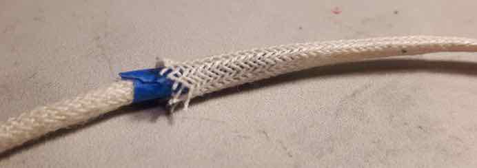
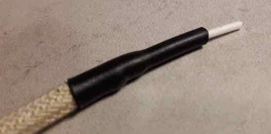
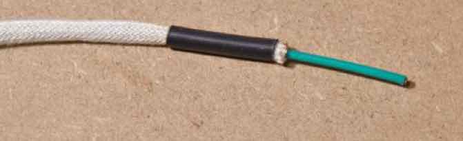
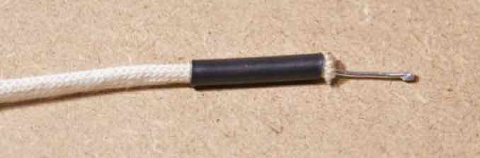
Both ends should look like this...
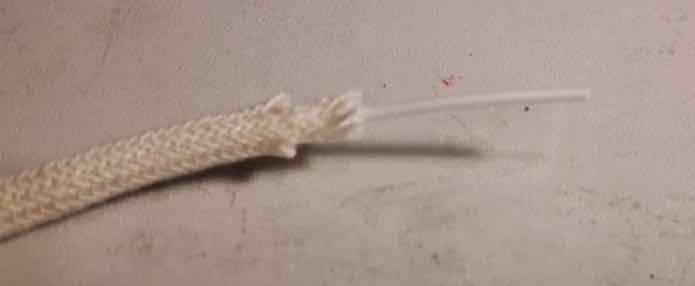
Cut a 3/4” length of the Heat Shrink (with adhesive) and stretch one end, using a pair of needle nose pliers
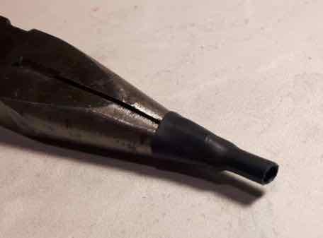
Place the heat shrink over the double layer of cotton sleeve
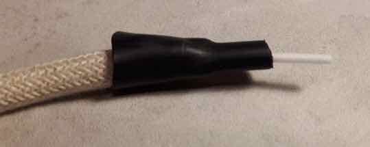
Apply heat to secure the cotton sleeve to the wire with the heat shrink
- try NOT to burn the cotton sleeve
Thread the live conductor into the Helix neutral and ground assembly and attach the spade connectors to each end
Attach the mains connectors and you are DONE!
So why do they work?
The power supply of an amplifier tends to be very well designed and built, because of the power requirements at play, whereas the more affordable source components, tend to be built to a price point and therefore the power supply is very often not as “capable” as the rest of the circuit.
The rest of the electrical components are very often just as capable as those in the amp, but in operation, their performance is impacted by the inadequacies of the power supply.
So if you use a very good power cable on a source component you can mitigate some of the inadequacies of its power supply.
The solid silver wire used for the Live conductor has an IACS rating of around 106% compared to copper at 100%
What is IACS? — it’s a measure of the conductivity of various metals relative to “Pure Copper”, a standard developed for copper wire producers, annealed copper having a rating of 100%
So the silver wire in these cables is able to respond more quickly to transient signal demands.
ALSO - the insulation on this particular silver wire has a dielectric constant (D.C.) of 1.4, compared to Teflon at 2.1.
The continual change in polarity of the alternating current charges and recharges the insulation much like the dielectric in a capacitor, which induces noise into the conductor. A lower D.C reduces the amount of noise generated internally within the conductor itself.
However, solid silver wire is very expensive, and I am a frugal being, which is why I have only selected it for power cables that will be used only on my source components.
But you could use multiple strands of the solid silver wire for the live conductor to increase the current handling capability - e.g. 4 x 18 gauge strands would equate to a 12 gauge conductor
What improvements did I observe?
- There was a significant improvement in the details of “venue acoustics” - i.e. echoes and reverberations
- dynamics were noticeably crisper
- the image was noticeably larger front-to-back and there was more precision of artist location within the image
- there appeared to be more “air” around each performer
- clarity was improved, i.e. you could hear more of the fine details and layers within the music
I recommend making the single 18 gauge cables...
ONLY - if your component draws less than 40 watts - WHY?
The 18 gauge solid silver wire is rated at around 1 amp - HOWEVER - transient spikes can result in significantly higher current draws, which can impact performance or even overheat the cable.
For components rated BETWEEN 40 - 80 watts - use 2 x 18 gauge SOLID SILVER WIRE (effectively 15 gauge).
FOR USE WITH AMPLIFIERS - you could use 4 X 18 gauge wire for the live conductor - that would effectively make it 12 gauge conductor.
Can I just Upgrade an existing 12 gauge HELIX Power Cable?
Yes - just replace the 12 gauge Live conductor with a single 18 gauge conductor
- HOWEVER - mark the cable in some way to identify that it has the small gauge live wire that is NOT suitable for amplifiers
NOTE: The 12 gauge wire used for the neutral and ground wire when upgrading a 12 gauge power cable in this manner, is NOT detrimental to cable performance if using the 18 gauge live conductor.
The Journey...
I’m a frugal person with a distinct dislike of overpaying for something as simple as a piece of wire!
I started making my own cables many years ago from Bulk cable with reasonably priced connectors.
I first tried Furutech bulk cable and then stumbled upon DH Labs, which I believe offers similar performance for about 1/3 the price - how could you not like that.
I then investigated a braided architecture which proved very effective, even using plain old Romex house wire.
Finally, I tried the Helix Architecture, which has proved to be the best performing power cable architecture to date.
I have now implemented this architecture on all my cables that have anything to do with audio.
What do they sound like?
The “HELIX IMAGE Power Cable” is a high performance power cable that allows connected components to perform to the best of their abilities.
They assist components in delivering ultra fast dynamic performance, exceptional clarity, expansive imaging and a very deep and exceptionally well controlled and very natural bass performance.
How Long is the Burn-In Period?
It is imperative that these cables are allowed adequate time to settle and burn-in...
- they will sound extremely good on initial installation
- after about 60 hours they allow more of the micro details in the form of venue specific reverberation captured in live recordings, or applied by very talented sound engineers, to clearly be heard.
The end of the Road?
My hope is that this design will be embraced and enhanced by the DIY Community and encourage them to experiment with different conductor materials and configurations to tailor the sound to their own liking.
For Helix cable spec’s please see Its More Than Just Numbers - Isn't It?
My Review System:
Custom built turntable with a Soundsmith Denon DL103 phono cartridge mounted on an Audiomods Arm with one piece silver litz harness + KLEI Absolute®Harmony RCA’s
Simaudio MOON LP5.3 RS phono stage
Bluesound Node 2i music server
Bryston B135 Integrated amp.
Gershman Acoustics Sonogram speakers.
 Give them a try - and - Enjoy The Music!
 ![]()
DIY Interconnect Cables - The "HELIX IMAGE" Interconnect
Now includes an updated Balanced design...
The “HELIX IMAGE Interconnect” represents the very latest developments in researching different wire types, geometries and materials.
The premise behind its helical geometry (or architecture) is eliminating parallel conductors, since...
- if two parallel conductors are in close proximity for an extended distance, and current is passed down them, then noise & distortions will occur within them.
Why would this matter? Isn’t the neutral is effectively connected to the “ground” ?
Well, the neutral conductor is actually connected to the neutral side of the circuit of both attached components.
Any noise that permeates through the neutral side of the components circuit, will have a negative impact on the connected components, resulting in distortions in the signal, which is ultimately amplified and output to the speakers.
Any noise in the signal conductor gets gets distorted even further through each stage and again amplified even further
In addition, parallel conductors are prone to Proximity & Skin Effects which alters the resistance of the conductor. affecting the transfer the signal
All of this impacts the phase between the left and right channels, which “smears” the mage.
The original helix design concept eliminates the parallel conductors and minimizes the noise, proximity effect and Skin effect to imperceivable levels, improving clarity and dynamic performance of the interconnect.
Since those early days, developments include the selection of various types of wire, gauge of wire and types of insulation, to bring us to this moment in time
One other nice feature of the helical design is the neutral conductor, being wound around the signal conductor, becomes a very effective shield against external RFI sources - in effect is is a Faraday Cage surrounding the signal wire - because it is connected to “ground” ![]()
But Shouldn’t The Two Conductors Be The Same Length?
If you look at the “roles” the two conductors play from the perspective of an attached components’ circuit diagram it becomes clear that cable length is immaterial and they can be made from different materials and gauges.
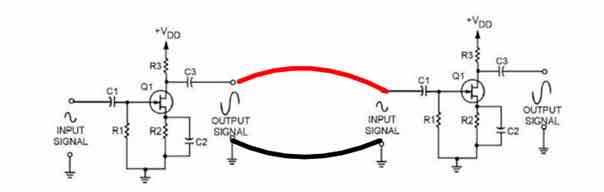
- The Signal Conductor transfers the signal
- The Neutral Conductor completes the circuit, BUT, it also connects the neutral sides of the two attached components
- Any “noise” present on the neutral conductor impacts the operation of BOTH components.
For more detailed information on cable design issues please read the three articles below that talk about the many problems that challenge cables builders.
They will provide a great deal of insight into the many parameters and design techniques employed to build cables that excellent in their performance.
https://www.psaudio.com/article/cables-time-is-of-the-essence-part-1/
https://www.psaudio.com/article/cables-time-is-of-the-essence-part-2/
https://www.psaudio.com/article/cables-time-is-of-the-essence-part-3/
How To Make Them...
FIRST: determine the “Direction” of the Helix for the wire you will use - see Inside The Helix Geometry.
The Single Ended IC Design...
The parts list is reasonably priced between $180 - $250 CDN for a 3ft ( or 1 meter) pair, depending on the RCA’s and wire selected - and all other parts can be purchased from many parts providers on the web.
Considering their exceptional sound quality I believe this price range to be excellent value.
You can upgrade or downgrade these parts if you wish, but the parts listed will provide exceptional sound quality.
I use an approximate ratio of 3:1 of Neutral:Signal conductor
e.g. for a 3ft Interconnect cable I use 9ft of Neutral Conductor
The quantities listed is for a single Interconnect cable i.e. one channel - so double them for a stereo pair
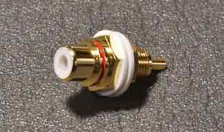
- RCA Plug: KLE Innovations Absolute Harmony RCA Plugs (SOURCE: KLE Innovations or local parts sources)
- Neutral Conductor: 9 ft of Mil Spec 16 AWG Silver Plated Copper Wire Green Cryo Treated (SOURCE: TAKE FIVE AUDIO - TFA)
- Signal Conductor: 3 ft of 20 gauge Duelund stranded Tinned Copper with Oil/Cotton insulation (Source: HiFi Collective).
- WBT 4% silver solder
Step 1.
I first wind the conductor around a 5mm-8mm metal rod. To assist with this I insert the rod into a variable speed hand drill and feed the conductor along its length.
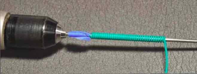
Once wound, the helix can be removed from the dowel.
Step 2
Insert the Duelund wire into the helix.
Space the windings over the length of the signal wire
Tighten the helix by twisting it, about an inch at time, along the length of the cable
OPTIONAL: You can place a small piece of Heatshrink tube at the end to allow the two small set screws to grip the cable.
NOTE: the signal wire will touch the side of the Helix, but it does not appear to impact sound quality.
Step 3
Soldering the KLE Innovations needs a little care to prevent excess heat from damaging the plastic housing
I use a chassis mount RCA jack and insert the RCA base into it in order to wick away excess heat
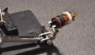
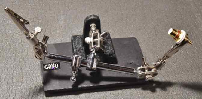
I also use a little “rig” to hold the parts while I solder
I’ve found that it is easier if I first solder the signal wire to the RCA plug first, followed by the neutral wire
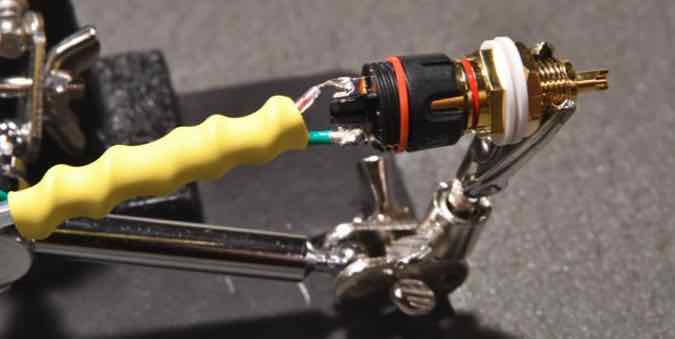
Install the housing of the RCA and tighten the screws
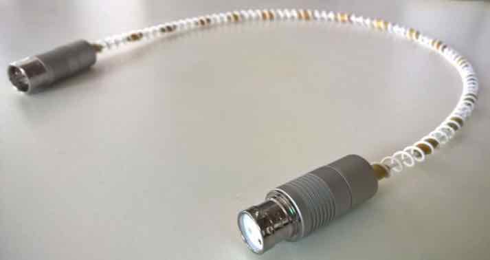
Assembly of the “HELIX IMAGE Mundorf” interconnect...
The HELIX IMAGE Mundorf Interconnect performs at a slightly higher performance level, which I recommend if you want to achieve the very highest levels of resolution. But the improvements may only be discernible when using higher-end components
The HELIX IMAGE Mundorf interconnect uses Mundorf Solid Silver/Gold(1%) wire without insulation for the signal wire.
- the construction is basically the same with a slight adjustment to install the Cotton Tube sleeve
- They really open up the image and presents a fuller, more detailed image with superb dynamics.
The design concept of the HELIX IMAGE Mundorf interconnect is the brainchild of a fellow DIYer, Ernst, of Austria.
Ernst experimented with the Helix Speaker Cables and found that the Insulation, heat shrink and expandable nylon sleeve previously used in the Helix design actually impacted the sound.
He used wood spacers to position the signal wire in the centre of an oversized Helix Coil, which “effectively” meant a large percentage of the dielectric was in fact air. Performance improved and he passed on his results/design to me.
After giving this some thought I felt that it could be adapted to the Interconnect using small 5mm wood beads to “insulate” the bare wire and to position the signal wires in the centre of the helix. This in fact worked very well provided exceptional imaging.
But I started yo look into the dielectric constant of other materials, and since the Duelund wire performed so well I wondered if it was due to the cotton insulation.
It turns out that Cotton has a dielectric constant of 1.3, which compared to the 1.4-1.5 of wood, should be more beneficial
And so the following Interconnect now provides the best performance of all the Helix cables built to date.
The construction technique is identical to the Duelund version above, but you have to install a cotton sleeve over the Mundorf bare wire...
I use 1/8” cotton expandable sleeve, cut to 3/4” shorter than the length of the signal wire, to cover it. To prevent the ends of he sleeve from unravelling I install a 3/4” long piece of Heat Shrink tube. The tube comes with adhesive on the inside which prevents slippage
I first insert a small piece of the Neutral wire into the end of the sleeve to prevent the tube from collapsing once the tube is heated
I then insert the Mundorf wire into the sleeve - with 3/8” being bare at each end
I then insert the signal wire + sleeve into the helix coil and attach the RCA plug and space the windings of the helix neutral to the length of the signal wire
TIP: use a small piece of masking tape over the end of the wire to hold the wire in place within the sleeve before inserting into the Helix coil
I do leave about 3/4” of the neutral windings at each end close together and cover it with a small piece of Heat Shrink tubing (without the adhesive) so the set screws in the housing of the RCA plug has a more solid base to grip
I also tighten the Helix down around the piece of hear shrink on the sleeve to hold the sleeve in place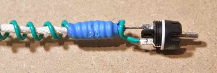
Finally I install the RCA plug housing and tighten the set screws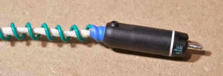
The result is exceptional reproduction of the musical signal, complete with an amazingly large image and the clarity of a live performance.
I leave it up to you as to which wire you select, but all the wires mentioned above will outperform most of the commercial products currently available
Did I try using Duelund or Mundorf wire for the Helix Neutral?
- I only use Duelund or Mundorf wires for for the signal conductor - not for the neutral Helix - it’s more affordable.
- BUT: I did try the Duelund wire as the neutral on an interconnect, but I found it did not improve sound quality over the Mil-spec wire, so I continue to use the Mil-spec wire for the neutral.
Can you use other brands of RCA?
NOT RECOMMENDED!
I recommend KLE Innovations Harmony RCA’s because of their stellar performance. Personally, I use the Absolute Harmony RCA because it is their best performer. I have used Furutech plugs, but the KLE Innovations product outperform the other RCA plugs I have tried, including Neotech Furutech and WBT RCA plugs.
Also, the properties of the KLEI Harmony RCA’s are very different from conventional RCA’s, such that they can be used on single ended SPDIF cables without experiencing the issues associated with conventional RCA’s not rated at the same impedance as the cable because their impedance exceeds 110 ohms.
e.g. “convention” states that a SPDIF cable should use an RCA plug of identical impedance
Primarily to reduce/eliminate internal “reflections” of the digital signal back down the cable
However, the KLEI Harmony RCA’S can be used on most digital cables regardless of the cables rated impedance value.
I also believe their higher impedance is responsible for their stellar analogue performance.
Can this cable be used for SPDIF purposes?
Absolutely! - it is an extremely adept SPDIF cable!
And I have found that the following cost saving adjustments do not impact SPDIF performance at all...
- KLEI Silver Harmony RCA plugs can be used in place of the more expensive Absolute Harmony RCA plug
- The Silver plated Mi-Spec wire is used for the signal conductor
To date, it is the best SPDIF cable I have used.
What do HELIX IMAGE Interconnects sound like?
The “HELIC IMAGE Interconnect” is a high performance cable with extremely high resolution capabilities.
They deliver a completely “uncoloured presentation” with ultra fast dynamic performance, exceptional clarity, expansive imaging and a very deep and exceptionally well controlled bass performance.
They excel in the delivery of one of the most realistic and compelling presentations of live recordings I have observed.
- The delicate nuances pertaining to the acoustic reverberations of instruments and voice within a live venue are faithfully reproduced in the most minute detail, with a precision placement of musicians and their instruments within their own “virtual space”.
My system components are quite modest by today’s standards. However my cables are all excellent performers and they work in harmony with the components to achieve an excellent overall “system performance” that exceeds it’s price point by a considerable margin.
Will the “HELIX IMAGE Interconnect” perform well on all systems?
Based on feedback from people who have made them for installation in some quite varied systems, including all tube, tube hybrid and solid state, so I have no reason to believe their performance will be anything less than stellar on most systems.
The HELIX IMAGE Balanced (XLR) Interconnect
For a 3ft stereo pair:
- 2 pairs of Neutrik NC3FXX-HA Male/Female XLR Cryo Treated - with Silver Plated Pins ( SOURCE: TAKE FIVE AUDIO - TFA)
- Neutral Conductor: 18 ft of Mil Spec 16 AWG Silver Plated Copper Wire Green Cryo Treated (SOURCE: TAKE FIVE AUDIO - TFA)
- Signal Conductor: 12 ft of 20 gauge Duelund stranded Tinned Copper with Oil/Cotton insulation (Source: HiFi Collective)
- WBT 4% silver solder
The “standard” Balanced XLR IC design is “basically” the same as single ended design with a simple modification.
A balanced cable requires two signal conductors
- one for the positive signal
- one for the negative signal
- gently twist the signal wires together - 0ne twist every 5-6 inches
- Wind the neutral wire around a 6mm rod
- Insert the signal wires into the Helix
- add XLR connectors and Voila - you have a Helix XLR Interconnect cable
NEW DESIGN: The “HELIX IMAGE Mundorf (XLR)” Interconnect
Fellow DIYer, Yordan from Bulgaria, sent me this “upgrade” to the original XLR Interconnect design using wood beads similar in principle to the single ended design above, while incorporating Ernst’s approach of eliminating the use of man made sleeving/heatshrink and incorporating wood beads spaced along the signal conductor
The material choices, design elements and construction techniques of this cable makes it a worthy “HELIX IMAGE Mundorf” XLR Interconnect
if you wish to apply Yordan’s modifications and elevate your cable to the version shown below you will need ...
- Mundorf silver/gold wire, 0.5mm dia, SGW105 Teflon Insulated for the signal wire
- Mundorf silver/gold wire, 1mm dia, SGW110 Teflon Insulated for the neutral Helix
- 20 - 6mm diameter x 15 mm long wooden beads
- Yordan uses Oyaide SS-47 solder for the signal wires and Mundorf Supreme 105 silver solder for the neutral
And Then...
- wind the neutral conductor in a 8mm diameter spiral around an 8mm dowel/rod, wide enough to accommodate the 6mm diameter Beads
- Twist the signal conductors together - one complete twist every 2 inches (5-6 cm)
- Insert the twisted signal wires into the beads and use glue to hold the beads in place
- Insert the signal wire+bead assembly into the helix coil
- add XLR plugs and VOILA!
Yordan has also contributed considerably to the development of the Helix range of cables.
Yordan’s comments on the performance of the XLR cables...
“there was a jaw dropping effect - the sound is on another level”
The Journey...
I’m a frugal person with a distinct dislike of overpaying for something as simple as a piece of wire!
I started making my own cables many years ago, but many of those utilized bulk cable from companies like Van den Hul and DH Labs.
I then investigated some of the more recent cable geometries such as tight twisted pairs, braiding and helix geometries.
My primary goal along the way was to keep the cost of materials to a minimum whilst achieving extremely high levels of performance.
When I first tried the early CAT6 version of the Helix design it was quite clear that it was going to be a very adept performer.
This observation supported my belief that the Helix architecture (or geometry) was an extremely effective approach to achieving excellent cable performance.
The early versions utilizing CAT6 as the neutral conductor were very good - just not “brilliant”.
Evolution to the HELIX IMAGE and HELIX IMAGE Mundorf has been gradual with significant period of testing and redesign
The improvements achieved with the latest modifications, over previous versions, were so good that I decided that a new name was warranted - voila...
the “HELIX IMAGE ” and HELIX IMAGE Mundorf was born!
The result:
a cable that actually competes with some of the very best cables in the audio world!
C’mon, Really?
- OK, I’ll let you be the final judge, but after listening to many cables I believe this to be the case

How Long is the Burn-In Period?
It is imperative that these cables are allowed adequate time to settle and burn-in, which is typically >300 hours.
- they will however sound extremely good on initial installation
- they may exhibit some loss in volume and image focus after 3-4 days continuous use, but will return to normal by day 6-7
- they will sound exceptional after around 200 hours, but they will get even better after 300 hours
- I have also found ongoing improvements occur up to approximately 600+ hours in the earlier versions
- The use of cable cookers will expedite this process - start with 100 hours cooking + 100 hours playing
The end of the Road?
My hope is that this design will be embraced and enhanced further by the DIY Community, and encourage them to experiment with different conductor materials to tailor the sound to their own liking.
- Since the original posting back in 2015, I have exchanged email with several fellow Diyer’s that have contributed to the Helix design.
- Some people that have contributed to the evolution of the Mark VII design, including: Ernst (Austria), Yordan and Evgeny (Bulgaria), Ghislain (Canada), Todd (USA), John (USA) and many others.
For Helix cable spec’s please see Its More Than Just Numbers - Isn't It?
My Review System:
Custom built turntable with a Soundsmith Denon DL103 phono cartridge mounted on an Audiomods Arm with one piece silver litz harness + KLEI Absolute®Harmony RCA’s
Simaudio MOON LP5.3 RS phono stage
Bluesound Node 2 music server
Brysyon B135 integrated amp
Gershman Acoustics Sonogram speakers.
Helix cables throughout
 Give them a try - and - Enjoy The Music!
 ![]()
ADDENDUM:
Audiogon Member Toddverrone has also tried these IC’s ...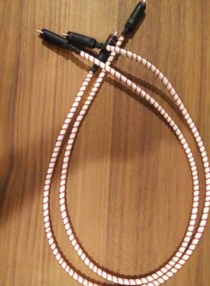
The Parts List :
- signal wire: OCC solid silver 24awg in cotton. 3' per cable
- neutral: OCC solid copper 20awg magnet wire. 2 x 9' per cable
- connectors: KLE pure harmony solid silver
- the white tube is a foamed teflon flexible tube that i ran the signal through. it's pretty amazing. it doesn't kink at all. it's called hyperflex tubing from vh audio
Todd’s Feedback...
I’m still listening to them, but initial findings on the helix ICs are incredibly positive.
More of the helix magic: less noise, greater clarity, better separation of sound sources.
Good stuff!