


DIY Power Cables - The "POWER HELIX"
I started looking at cable architectures a while back, initiated by an experience with a home lighting repair.
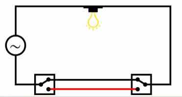
I was installing a new two way switch on a hallway light, the type with a switch at each end of the hallway (see diagram below). I decided to play it safe and use my multimeter to verify the open/closed position of the switches.
With the switch in the OFF position everything checked out, but with the switch in the ON position I found that there was a reading of 42 volts on what was supposed to be the "dead conductor" i.e. the red conductor in the diagram below.
I found an article on the web which verified that in this particular situation it is common for one of the conductors in standard household power cable to register an "induced voltage".
Turns out my digital multi-meter had such a high resistance that it drew no current so the reading was unusually high. However, my analogue meter, which draws a little more current still registered a reading of 13 volts.
That’s still - a lot of "noise".
In the case of “conventional” power cable architectures, the live conductor and the neutral conductor tend to be side by side in extremely close proximity for the length of the cable, therefore I consider it reasonable to assume that noise, at the amplitude measured above, will be induced from the signal conductor into the neutral conductor.
This “pollution” of the neutral conductor may also take place on the ground conductor also and depending on the design of a components circuit, have an adverse effect on sound quality.
The premise of the helical design concept eliminates the parallel conductors and minimizes induced noise to imperceivable levels!
For more theory pertaining to this see Electromagnetic Interference - Considerations in Structured Cabling Systems from Siemens
But First My Disclaimer:
DO NOT attempt any of the assemblies detailed below unless you are an experienced Electrical Professional OR Electronics Hobbyist - otherwise consult a technician!
YOU ARE RESPONSIBLE: for following local electrical codes. Failure to do so may result in personal injury, damage to equipment, or power cable failure which can result in fire.
YOU ARE RESPONSIBLE: for ensuring the cable selected is suitably rated for the power requirements of the component(s) it will be attached too !
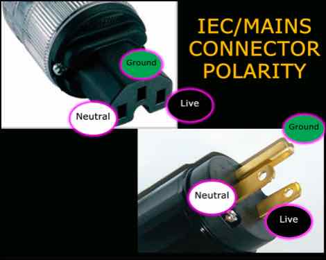
YOU ARE RESPONSIBLE: for ensuring the IEC/Mains connectors are installed observing the correct polarity !
- failure to do so can result in poor operation, component failure or electric shock.
YOU ARE RESPONSIBLE: for ensuring the dielectric strength of the insulation on ALL conductors used, meets or exceeds local codes!
e.g. In North America - 600v at 200 Celsius for 120v 50/60 Hz supply
These Power cables are only to be used for Home Audio Purposes and must not subjected to harsh environments and frequent handling, which generally require additional protective coverings.
The materials mentioned below comply with most codes for NORTH AMERICA ONLY!
Electrical codes in other countries may require the selection of different materials, therefore YOU ARE RESPONSIBLE for following those local electrical codes.
YOU are responsible for ensuring “power related” assemblies are safe to use!
Materials...
The materials listed below will build a 6ft power cable that is suitable for use with Power Aimplifiers rated up to 600 watts.
- 6 ft of Furutech FP-3T762 bulk cable, OR
- 6 ft of DH Labs Power Plus bulk cable
- 28 feet of stranded Mil Spec 12 AWG Silver Plated Copper Wire, Cryo Treated, Red - available from Take Five Audio (TFA)
- 14 feet of green 12 gauge mains copper wire from Home Depot
- 2 feet of 1” black Heat Shrink sleeve
- 7 ft of 3/8” (10 mm) expandable nylon sleeve (outer sleeve)
- 7ft of black 1/4” expandable nylon sleeve (for Live conductor - see below)
- 1 Pair of SONAR QUEST CRYO Ag Audio Grade Silver plated IEC plug + US main plug
- lead free solder suited for electronics use - or WBT 4% silver solder can also be used
- 10-12 gauge copper spade/fork connectors
- For Spade/Fork terminals take look at the Grainger Web site and in their options check box select TERMINAL TYPE: Standard, WIRE RANGE: 12-10 gauge, INSULATION TYPE: Bare and SEAM: Butted
- Fork Terminals - Spade Terminals - Grainger Industrial Supply
- 1 6ft x 1/4” fibreglass rod - available from Home Depot

The Sonar Quest connectors have heavy Silver plating on pure copper contacts that provide excellent clamping and transmission of electrical current - available from ebay
I use an approximate ratio of 2.5:1 of Ground/Neutral:Live conductor
e.g. for a 6ft power cable I use 14ft of Ground and 14ft of Neutral Conductor
The Live Conductor...
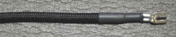
I have tried many different “wires” for this role, and without question the best have been the conductors found in either of the two bulk cables listed above.
Granted, you do have to “butcher” some very nicely made bulk cable, however, you can make three power cables from one length of bulk cable. ![]()
First, strip of the outer sleeve of the bulk cable and the shield and remove the internal conductors.
Using just one of the internal conductors - Attach a 10 gauge spade connector, crimp in place and apply solder
Place the 1/4” black nylon sleeve over the length of the Live Conductor
Attach a small piece of 5/16” heat shrink sleeve at each end to hold the expandable sleeve in place
DO NOT apply the second spade connector just yet!
The Neutral Conductor...
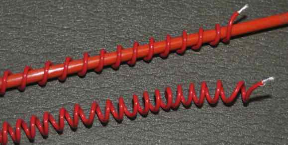
The Neutral Conductor is made from two lengths of the Mil Spec 12 AWG Silver Plated Copper Wire listed above.
Why two pieces? - this effectively make the neutral wire a 9 awg conductor, which I have found performs much better, resulting in faster dynamics, better bass performance and control and more natural imaging.
Cut the 28 ft length of wire into two equal length pieces.
On the 1/4” rod, wind the neutral conductor in a helix configuration, space the windings about 1/4” apart and remove from the rod.
Repeat the winding process with the second piece of wire.
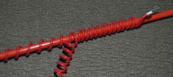
With the second coil of wire still on the rod...
- Attach the first coil to the second coil with a 10 gauge spade connector
- Wind the first “coil” of wire between its windings as shown below
Remove the two “intertwined” coils from the rod
The Ground Conductor...
On the 1/4” rod, wind the green GOUND conductor in a helix configuration, space the windings about 1/4” apart and remove from the rod.
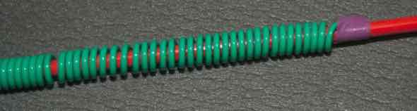
Thread the Live conductor through the centre of the red coil(s)
Attach a second 10 awg spade connector on free end of the Live conductor, crimp and solder in place.
Attach a second 10 awg spade connector on the two free ends of the neutral conductor, crimp and solder in place.
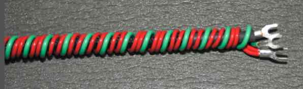
Wind the green wire between the “double winding” of the neutral conductor as shown below.
Place 12 awg spade connectors on both ends of the ground conductor, crimp and solder in place
Place the expandable nylon sleeve over the cable assembly and cut to length
Cut two adequate lengths of 1” heat shrink tubing and place over the nylon sleeve
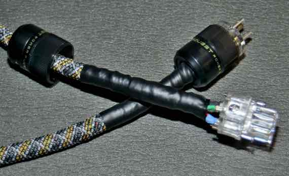
Attach the Sonar Quest connectors to the cable assembly ensuring you adopt the correct polarity!!!
Position the heat shrink over the ends of the outer sleeve and apply heat
Secure the connector covers in place to complete the cable assembly
Assembly Notes...
If you feel the use of Furutech or DH Labs bulk cable is a little too “extravagant”, you can opt to use a 6ft length of the stranded Mil Spec 12 AWG Silver Plated Copper Wire. In which case I would reduce the upper limit of an attached amplifier to 500 watts.
Why do I use spade connectors? -
- First, trying to attach the mains/IEC connectors to a 10 gauge cable is very difficult,
- More importantly - the spade connectors prevent detachment from the connectors in the event of unforeseen stress being placed on the connectors.
- I have also found that the spade connectors actually improve sound quality.
For a more secure crimped joint, I always crimp from the back - as shown in the image below, which prevents the collar from opening.
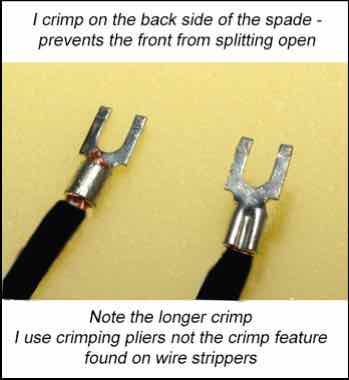
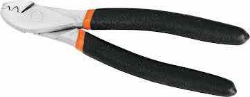
I use pliers as shown in this image that applies an extended crimp along the whole length of the spade connectors collar
Cables that are more suited to source components can use lighter gauge conductors, but be sure to determine their power requirements and select a gauge that can handle it with headroom to spare.
Can you use other brands of IEC/Mains connectors?
Of course. Some people might prefer to use Furutech, or Oyaide high quality connectors.
Others may prefer to use something more reasonably price, like the Vanguard range of connectors.
I believe the Sonar Quest connector line provides exceptional sound quality for a reasonable price.
The Journey...
I’m a frugal person with a distinct dislike of overpaying for something as simple as a piece of wire!
I started making my own cables many years ago from Bulk cable with reasonably priced connectors.
I first tried Furutech bulk cable and then stumbled upon DH Labs, which I believe offers similar performance for about 1/3 the price - how could you not like that.
I then investigated a braided architecture which proved very effective, even using plain old Romex house wire.
Finally, I tried the Helix Architecture, which has proved to be the best performing power cable architecture to date.
I have now implemented this architecture on all my cables that have anything to do with audio.
What do they sound like?
The “POWER HELIX” is a high performance power cable that allows connected components to perform to the best of their abilities.
They assist components in delivering ultra fast dynamic performance, exceptional clarity, expansive imaging and a very deep and exceptionally well controlled bass performance.
How Long is the Burn-In Period?
It is imperative that these cables are allowed adequate time to settle and burn-in...
- they will sound extremely good on initial installation
- after about 60 hours they allow more of the micro details in the form of venue specific reverberation captured in live recordings, or applied by very talented sound engineers, to clearly be heard.
The end of the Road?
I have decided to end this particular power cable “obsession” with the “POWER HELIX” simply because...
- the cost of better materials is making them significantly more expensive
- I believe any improvements using better materials will probably be marginal from this point onwards
My hope is that this design will be embraced and enhanced by the DIY Community and encourage them to experiment with different conductor materials and configurations to tailor the sound to their own liking.
My Review System:
Custom built turntable with a Soundsmith Denon DL103 phono cartridge mounted on an Audiomods Arm with one piece silver litz harness + KLEI Absolute®Harmony RCA’s
Simaudio MOON LP5.3 RS phono stage
Bluesound Node 2 music server
NAIM 5i integrated amp (with passive pre-section).
Gershman Acoustics Sonogram speakers.
KLE Innovations gZero6 Speaker Cables
 Give them a try - and - Enjoy The Music!
 ![]()