


Power Cable Construction Techniques
DO NOT attempt any of the assemblies detailed below unless you are an experienced Electrical Professional OR Electronics Hobbyist - otherwise consult a technician!
YOU ARE RESPONSIBLE: for following local electrical codes. Failure to do so may result in personal injury, damage to equipment, or power cable failure which can result in fire.
YOU ARE RESPONSIBLE: for ensuring the cable selected is suitably rated for the power requirements of the component(s) it will be attached too !
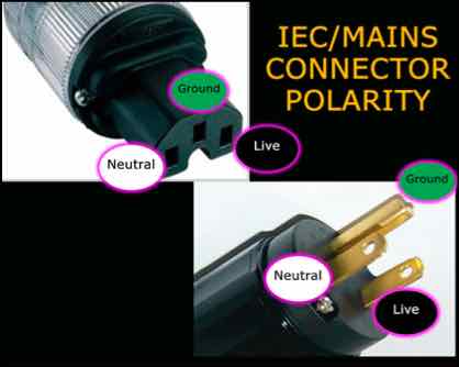
YOU ARE RESPONSIBLE: for ensuring the IEC/Mains connectors are installed observing the correct polarity !
- failure to do so can result in poor operation, component failure or electric shock.
YOU ARE RESPONSIBLE: for ensuring the dielectric strength of the insulation on ALL conductors used, meets or exceeds local codes!
e.g. 600v (minimum) at 200 Celsius in Canada for 120v 50/60 Hz supply
YOU ARE RESPONSIBLE for following local electrical codes. Failure to do so may result in personal injury, damage to equipment, or power cable failure which can result in fire.
These Power cables are only to be used for Home Audio Purposes and not subjected to harsh environments that may require additional protective coverings.
YOU are responsible for ensuring power related assemblies are safe to use!
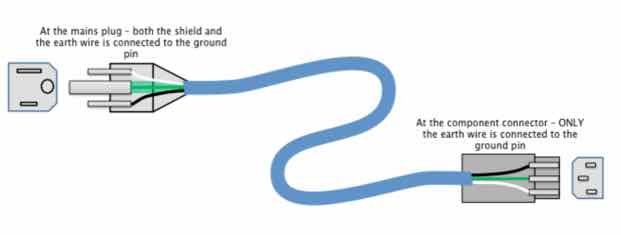
“Floating Screen" Power Cable Construction Details...
This technique requires a cable that has a separate shield.
I am not aware of any company that adopts this construction technique, therefore DIY is required
The theory of this technique is that any induced RF/Noise is ONLY flowed to the mains earth, away from the power supply of the component it is attached to.
- For added safety/security I crimp and solder spade connectors to the conductors - even on the ROMEX cables
- this ensures maximum electrical contact and the wire should remain securely attached
Helix Power Cable Construction Details
Prior to trying this design I had tried several different bulk brands from Furutech and DH Labs. I then tried braiding cables, which performed much better than the bulk cables.
However, the helix architecture far exceeds the performance any of the above cable architectures and elevates the abilities of my components to a whole new level.
I’ve also found that my solid state components run significantly cooler
The architecture of these cables makes the need for shielding redundant...
- the helix Ground and Neutral conductors interrupts the induction process and effectively shields the live cable from EMI/RFI
- the helix winding of the Neutral conductor prevents noise being induced into it by the current flowing in the Live Conductor
I use an approximate ratio of 2.5:1 of Ground/Neutral:Live conductor
e.g. for a 6ft power cable I use 15ft of Ground and 15ft of Neutral Conductor
Materials...
For this cable, only the Live conductor needs to be made from high quality copper or silver.
- All my cables utilize a conductor extracted from a length of Furutech or DH Labs Bulk cable.
- DH Labs is much easier to extract the conductors from the protective outer sleeving and it’s approximately 65% cheaper
The Neutral conductor was purchased from Take Five Audio and is silver plated 12 gauge Mil-Spec copper cable
The Ground conductor was purchased from a local home improvements store (Home Depot)
The spade connectors I use are available from most electronics supply stores and generally cost $1.20 for a pack of 10 - just ensure they are copper under the plating - their effect is minimal
For all solder joints I use WBT 4% silver solder
The Mains/IEC connectors are Sonar Quest Silver Plated Copper available from Ebay
PLEASE NOTE: although the photos below show spade connectors already attached - in reality it is much simpler to attach them in Step 5 below.
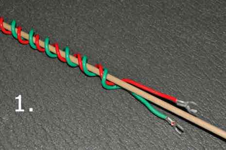
1. Using a wooden dowel approximately 5-6 mm in diameter, wind the Ground and Neutral conductors in a helix formation
- the wire will retain the helix shape after the tension has been released
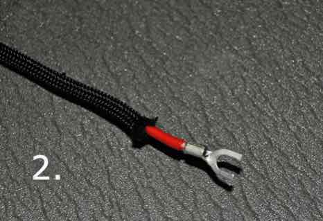
2. Insert the live conductor into expandable nylon sleeve
The purpose of inserting the live conductor into the expandable nylon sleeve is two fold
- provides additional insulation around the live conductor
- provides additional space between the Live and Ground/Neutral conductors which further reduces EMI
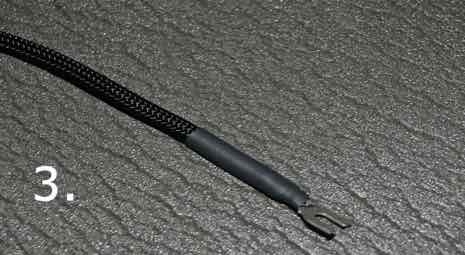
3. Secure the sleeve with heat-shrink
4. Insert the insulated live conductor into the neutral/ground helix assembly and secure with Heat-Shrink tubing

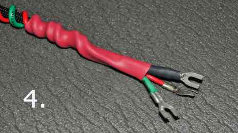
5. Finishing...
- Insert the cable assembly into decorative expandable nylon sleeve
- Secure with Heat-Shrink Tubing
- Attach spade connectors - crimp and solder spade connectors for added safety
- Attach IEC/Mains connectors
- Ensure the correct polarity is maintained!
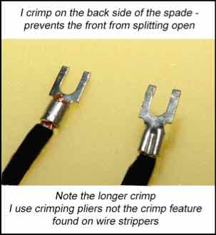
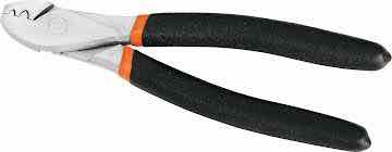
I use purpose built crimping pliers similar to those above
WARNING:
DO NOT attempt any of the assemblies detailed above unless you are an experienced Electrical Professional OR Electronics Hobbyist - otherwise consult a technician!
YOU ARE RESPONSIBLE: for following local electrical codes. Failure to do so may result in personal injury, damage to equipment, or power cable failure which can result in fire.
YOU ARE RESPONSIBLE: for ensuring the cable selected is suitably rated for the power requirements of the component(s) it will be attached too !
YOU ARE RESPONSIBLE: for ensuring the IEC/Mains connectors are installed observing the correct polarity !
- failure to do so can result in poor operation, component failure or electric shock.
YOU ARE RESPONSIBLE: for ensuring the dielectric strength of the insulation on ALL conductors used, meets or exceeds local codes!
e.g. 600v (minimum) at 200 Celsius in Canada for 120v 50/60 Hz supply
YOU ARE RESPONSIBLE for following local electrical codes. Failure to do so may result in personal injury, damage to equipment, or power cable failure which can result in fire.
These Power cables are only to be used for Home Audio Purposes and not subjected to harsh environments that may require additional protective coverings.
YOU are responsible for ensuring power related assemblies are safe to use!